|
 Page
4 Page
4
|
Cylinder
Heads: The Ruthless Pursuit of Power
 |
|
|
This graph of the intake air flow in both LS1 and LS6 intake ports clearly shows the air flow stall discussed in the text. Graphic: author.
Click Image For Larger View & PDF Print File |
|
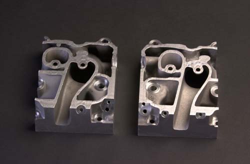
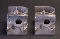
The same basic, performance-oriented characteristics of the LS1 head are used in the LS6 unit: 356-T6 aluminum casting, replicated ports (which offer the charge air a straight shot down to the intake valve), 15° valve angle, 2.00-inch intake valves and 1.55-in exhausts with three-angle faces. Additionally, the valve seats, head bolt and rocker stud bosses and oil return holes located such that they impact the intake ports as little as possible.
The major change in the LS6 intake port was alteration of its "short turn" or "short side" radius, the area of the port just upstream of the valve where the port floor curves down to the valve seat. The LS1 port suffered an air flow "stall" at high valve lift, induced by the short-turn radius and the goal was to eliminate that.
Ron Sperry, one of GM’s top, racing cylinder head guys during the 1980s, lead the team that did the 1997 LS1 head. One of the restrictions put on Sperry was: whatever he did with the intake port, injector targeting, which affects idle quality and exhaust emissions, was to be the prime concern. Ideally, port-injected engines should have injectors squirting fuel straight down the port, directly on the back of the hot intake valve. The temperature helps vaporize the fuel and the turbulence of the charge air blowing around the valve does the rest. For least emissions, we want really good vaporization.
|
 |
| |
A vertical view of the same two intakes shows the LS6 (left) has a port that is taller at the entrance but wider in the mid-section, thus preserving cross-sectional area. The LS1 port
does not share that characteristic.
Photo: GMPT Communications
Click Image For Larger View |
While Sperry did a lot of cool stuff with the original LS1 intake port, a compromise he was forced into was port walls that didn’t interfere with injector targeting. The fear was: if fuel contacted walls, it would end up as droplets or pool on the port floor. Anything other than a fine spray burns poorly and causes exhaust emissions to go up. To keep injector spray off port walls; LS1’s port floor was flat, low and had a short-turn radius tighter than was ideal for optimum performance.
After the LS1 release, Ron Sperry went back to GM Motorsports and Dennis Gerdeman became the Gen III’s cylinder head ace. During the late-’90s, the ruthless pursuit of power drove continued research into effects of intake port air flow dynamics and injector control software algorithms. This research showed injector targeting to be less important than originally believed.
For the LS6 intake port development, Gerdeman raised the port floor to recontour and soften the short-turn radius. That improved flow as it transistioned into the combustion chamber. When air flows though a port of varying cross-section, such as the LS1’s, there are localized fluctuations in flow velocity which reduce efficiency. In the interest of better consistency in cross-sectional area, the mid-section of the LS6 port was widened and its roof was raised. Negative effects of these changes on injector targeting and emissions were addressed with improved fuel control software and calibration.
 |
|
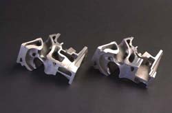
Side view cuts of the LS6 (left) and LS1 exhaust ports, again, show a smoother short-turn radius. On the piece at left you can also see some of the change to the combustion chamber. Note how the chamber wall in around the spark plug has been moved in, towards the valves and the roof has been lowered. Photo: GMPT Communications
Click Image For Larger View |
|
At high valve lift, flow improved. At .550-in. lift, just slightly more than the LS6’s maximum, flow jumped 10%. That GM validated the flow increase at .550 lift means the port has additional potential, given more camshaft. Is this a clue to what’s coming in LS6 for 2002? I’d say it’s a very good bet. Is this a hint to the aftermarket camshaft industry? That, too.
The LS6 combustion chamber is quite different from that in LS1 heads. The compression ratio (CR) gains four-tenths of a point to 10.5:1, but getting there wasn’t easy. A CR increase has a hydrocarbons (HC) exhaust emissions penalty, but GM wanted the payoff: more power, increased thermal efficiency and better fuel economy. The addition of the small, auxiliary, catalytic converters (engineers call them "pre-catalysts" or "pup cats") required for the Corvette to meet the LEV standard also allowed the engine the small increase in HC from the higher compression.
Dennis Gerdeman’s challenge with the chamber was to increase compression by reducing its size but without shrouding the valves. When a valve is "shrouded," the adjacent combustion chamber wall is too close when the valve is open and the closeness of that wall presents a restriction to air flow between the wall and the valve face. Obviously, shrouded valves reduce performance.
|
 |
| |
This
view of the exhaust port exits clearly shows the LS6’s
pronounced "D-port".
Photo: GMPT Communications
Click Image For Larger View |
Compared to the LS1, the roof of the chamber in the new head was lowered. This not only decreased chamber size, which increased CR, but it improved air flow over the short-turn radius. Additionally, lowering the roof slightly unshrouded the valves which enhanced flow into the chamber. So, he increased compression and unshrouded the valves. Dennis Gerdeman can do my cylinder heads any day.
The LS1 exhaust port was also revised with the same goals: improve short turn radius and make cross-sectional area more consistent. The port exits were also given the pronounced D-shape that many racing cylinder heads use. The changes to the exhaust ports netted about a 10% improvement in high lift flow.
There were some other changes to the cylinder heads that were driven by the revised ports and combustion chambers. Obviously, coolant passages had to be revised. Also, the oil drain back holes were altered to clear the new port designs.
One last word on the LS6 head: last year, right after a print version of this article went to press in GM High-Tech Performance Magazine, we heard rumors that Mallet Motorsports consulted with GM Powertrain on LS6 cylinder head development. When we contacted GMPT to confirm that, John Juriga surprised us by saying an aftermarket tuner did assist with the LS6 head, however, it was not Mallet, but Lingenfelter Performance Engineering.
The basic Gen 3 head architecture is quite good so early in the development program, engines with prototype LS6 heads were well over the LS1’s 345hp but not quite the 375 GM Powertrain and the people at Corvette wanted. John Juriga picks up the story, "We had to meet LEV emissions standard in ‘01, which meant adding "pup" converters. That added back-pressure which took our numbers down to 360 or so....not good enough.
We had friends at LPE and we knew they were porting our LS1 heads for their customers. We asked them to do some porting work for us. Our air flow guys saw this as a challenge and stepped up to the plate to work in parallel on a porting project of their own.
Some of what LPE did was not "production feasible" and we had to be content with an as-cast port vs. a
CNC-machined port, but LPE had some good ideas which did much to spur our guys on and offer us some perspectives we didn’t see previously. Bottom line: LPE did help us in our development and that made our production heads better."
We offered LPE’s communications contact, Jason Haines, a chance to comment on this. He acknowledged LPE’s role in the project but declined to be interviewed about it for this article stating LPE’s agreement with GM precludes any discussion of its work on the LS6.
Guess John L.’s folks know their Gen III cylinder head stuff pretty well.
Additional
Changes in the Intake and Exhaust Tracts.
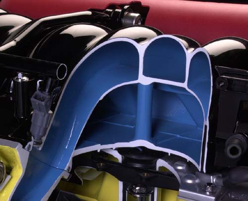
A unique Gen III item is the composite ("plastic") intake manifold. Plastic intakes are great for car companies because of low mass, low cost of materials and cheap manufacturing. The downside, a big difference between them and aluminum or iron manifolds, is the high cost of tooling. Car companies justify that by spreading the cost over a huge run of parts. As the LS1 went to production, GMPT already knew more performance would come from a revised intake manifold, however, the cost of retooling was so high, it waited for the next iteration of the complete engine to make the investment. Cost is, also, why the performance aftermarket has, to date, not offered intake manifolds for the Gen III.
|
 |
| |
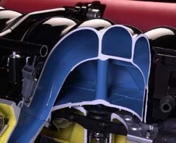
A cutaway close up of the front of the LS6 intake manifold plenum. Note that floor of the intake now is near flush with the top of the valley cover. This increase in volume, makes the new manifold 10hp to the better. Photo: GMPT Communications
Click Image For Larger View |
The biggest change in the LS6 intake was an increase in plenum volume accomplished by dropping the plenum floor as low as allowed by the engine block valley cover. Additionally, sharp edges at the junction of the intake runners and the plenum were smoothed. Some dead air pockets (areas of no flow) were eliminated. This new manifold is worth 10 horsepower, just by itself. The new intake is so good, it’s not only on the LS6, but it replaces the ’97-’00 LS1 intake, too.
The other changes for the LS6 are the higher-capacity mass air flow
(MAF) sensor from the 6.0-liter, truck engine. It’s worth 2-3hp and its integral intake air temperature
(IAT) sensor simplifies the engine controls and reduces cost. The LS6 also uses a different air filter assembly capable of slightly more flow.
The exhaust manifolds on the LS6 and 2001 LS1s are new cast iron items. Previously, the LS1 used a double-wall, fabricated, stainless-steel manifold. Most ’97-’00 LS1s had cats downstream in the exhaust under the floor. Double-walls, available only with a fabricated manifold, were required to retain exhaust heat in the interest of quicker light-off of the catalytic
convertors. The addition of pup cats, immediately below the exhaust manifolds on ’00 California cars and all ’01s, eliminated the need for the stainless manifolds.
The new iron manifolds offer improved exhaust flow compared to the stainless units but, currently, the LS6 doesn’t need the improvement. There will be further performance enhancement for MY02, enough that the extra flow will be needed. The iron manifolds offer better durability, too. They don’t crack at welds as can stainless manifolds and, believe it or not, because of the type of iron used, they will tolerate a higher level of exhaust heat. There is a weight penalty of about 4.5 lbs., but that is offset by mass reduction elsewhere in the Corvette platform.
|